
Advanced Pinball Lamp Controller
Capcom Hardware Installation
1. Turn off power to the game and wait 10 minutes.
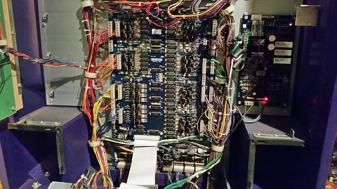
2. Remove the translite from the game and lower the speaker panel as shown.
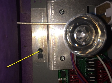
3. If you are installing in a Big Bang Bar, I would also suggest removing the fluorescent lamp and bracket. Use the male-female standoff included in the extension cable pack and thread the male end into the hole in the game that is normally used for the left end of the fluorescent lamp bracket. The existing screw can now be used to mount the lamp bracket , giving a bit more clearance under the bracket so that the LED OCD will fit.
4. The LED OCD board is intended to mount to the left of the power driver board and as low as possible.
5. The existing metal standoffs in the game can be used with some of the holes along the right edge of the LED OCD board.
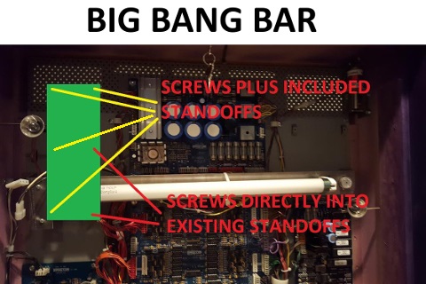
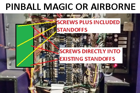
6. Use three of the included screws and the three hex standoffs in the remaining holes as shown.
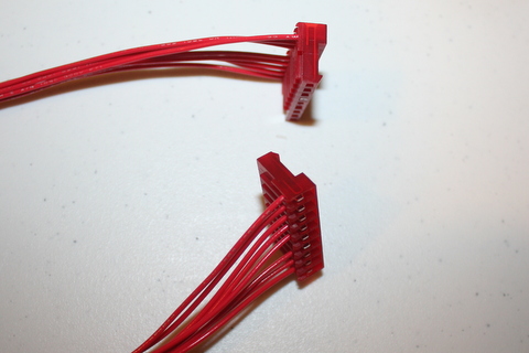
7. The row 'A' (red, thin wire) cables can be identified by the 9-pin (with keys at pin 4) connectors on opposite ends of the cable. There will only be one of these unless you are installing in a Big Bang Bar and purchased the additional extension pack.
8. Disconnect the lamp matrix row 'A' connectors, which are connected to J1 and J2, from the power driver board.
9. They need to be connected to J11 and J12 of the LED OCD board. If they reach as is (Pinball Magic or Airborne), just plug them in directly. If not (Big Bang Bar), use one of the row 'A' cables and one of the matching Z-connectors to extend each cable.
10. Connect one end of one of the row 'A' cables to J1 of the LED OCD board.
11. Connect the other end of the row 'A' cable to J1 of the power driver board.
12. Secure the cable using any available cable clips.
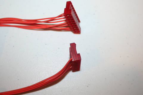
13. The row 'B' (orange, thin wire) cables can be identified by the 9-pin (with keys at pin 3) connectors on opposite ends of the cable.
14. Disconnect the lamp matrix row 'B' connectors, which are connected to J4 and J5, from the power driver board.
15. They need to be connected to J14 and J15 of the LED OCD board. If they reach as is (Pinball Magic or Airborne), just plug them in directly. If not (Big Bang Bar), use one of the row 'B' cables and one of the matching Z-connectors to extend each cable.
16. Connect one end of one of the row 'B' cables to J4 of the LED OCD board.
17. Connect the other end of the row 'B' cable to J4 of the power driver board.
18. Secure the cable using any available cable clips.
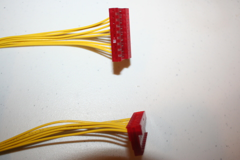
19. The column 'A' (yellow, thin wire) cables can be identified by the 9-pin (with keys at pin 6) connectors on opposite ends of the cable.
20. Disconnect the lamp matrix column 'A' connectors, which are connected to J6 and J7, from the power driver board.
21. They need to be connected to J16 and J17 of the LED OCD board. If they reach as is (Pinball Magic or Airborne), just plug them in directly. If not (Big Bang Bar), use one of the column 'A' cables and one of the matching Z-connectors to extend each cable.
22. Connect one end of one of the column 'A' cables to J6 of the LED OCD board.
23. Connect the other end of the column 'A' cable to J6 of the power driver board.
24. Secure the cable using any available cable clips.
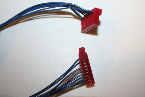
25. The column 'B' (blue, thin wire) cables can be identified by the 9-pin (with keys at pin 7) connectors on opposite ends of the cable.
26. Disconnect the lamp matrix column 'B' connectors, which are connected to J9 and J10, from the power driver board.
27. They need to be connected to J19 and J20 of the LED OCD board. If they reach as is (Pinball Magic or Airborne), just plug them in directly. If not (Big Bang Bar), use one of the column 'B' cables and one of the matching Z-connectors to extend each cable.
28. Connect one end of one of the column 'B' cables to J9 of the LED OCD board.
29. Connect the other end of the column 'B' cable to J9 of the power driver board.
30. Secure the cable using any available cable clips.
31. One end of the ground (black) cable has two 7-pin connectors. The other has one 4-pin connector.
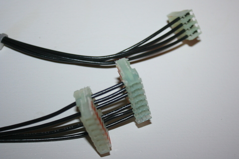
32. Connect the 4-pin connector to J3 of the LED OCD board.
33. If there is a connector already connected to J3 of the power driver board, remove it first.
34. Connect one of the remaining connectors of the provided ground cable to J3 of the power driver board.
35. If you disconnected a connector from J3, insert the provided 7-pin Z-connector in the remaining connector of the ground cable, then attach the connector you removed to the other side of the Z-connector.
36. Secure the cable using any available cable clips.
37. One end of the power (yellow, thick wire) cable has two 6-pin connectors. The other has one 5-pin connector.
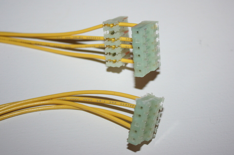
38. Connect the 5-pin connector to J8 of the LED OCD board.
39. If there is a connector already connected to J8 of the power driver board, remove it first.
40. Connect one of the remaining connectors of the provided power cable to J8 of the power driver board.
41. If you disconnected a connector from J8, insert the provided 6-pin Z-connector in the remaining connector of the power cable, then attach the connector you removed to the other side of the Z-connector.
42. Secure the cable using any available cable clips.
43. You can now turn on the machine. Verify that D1, D2, and D3 are lit solid on the LED OCD board. D4 and D5 should blink slowly (1 second on, 1 second off).
The insert lights should work, but they will be running at default settings and can be reconfigured for best results.
PC Software and USB Cable
You have the option of using PC Software and a mini-USB cable to change settings on the board.
1. Turn off power to the game and wait 10 minutes.
2. Connect the a mini-USB cable to the mini-USB connector J5 on the LED OCD board.
You are now ready for software installation.