
Advanced Pinball Lamp Controller
GI OCD Williams System 11 Hardware Installation
NOTE: GI OCD for System 11 is designed to be a replacement for the existing relay boards. Unfortunately, it is not plug and play. Installation will require tracking down the correct connection point yourself, desoldering wires, soldering new wires, adding connectors that are not included in the kit, etc. Only experienced modders should attempt this installation.
1. Turn off power to the game and wait 10 minutes.
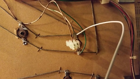
2. Find the relay you want to replace. First, I will be replacing the one on the back side of the backbox light board in a Whirlwind.
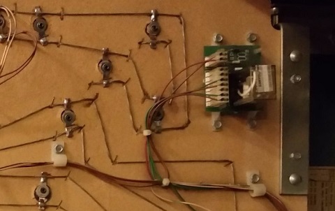
3. There are three separate strings of lights here. The one on the top is on constantly. We want to leave that as-is. That string then runs into the relay that is shown to allow the string on the left to be controlled. The string on the right is also controlled by the same relay board, but it is a bit simpler since it doesn’t have an “always-on” portion. We’ll start with that one.
4. The solid green wire already runs through the relay, but the white-green one is connected directly to the GI string. We need to disconnect that, and run it through the new board. Here is where it’s connected.
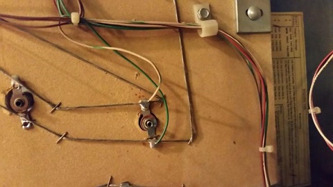
5. Desolder this wire and add a new wire that will be used to return power from the new board to the GI string.
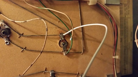
6. The same sort of thing needs to be done with the controlled portion of the purple string.
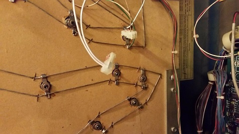
7. Add connectors to the other end of the wires. Both of the original wires, which come from the transformer, go into the input side of the new board, so they need to share a connector.
8. The two newly added wires will carry the controlled power from the new board to the GI strings, so those will also share a connector.
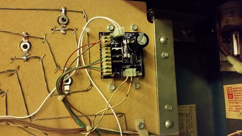
9. You’re now ready to install the board. It’s really pretty simple once the wires have been modified.
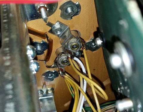
10. Whirlwind has a total of three GI relays. One is on the back of backbox light board, and the other two are under the playfield. Those ones under the playfield only control a single string of lights, but they are much more difficult to track the route of the wires since they are bundled in the harness.
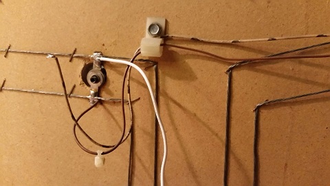
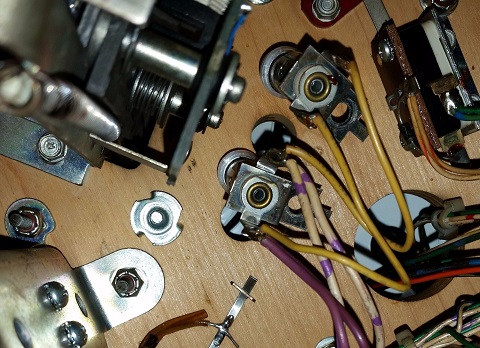
11. Here is the location where I tapped into the string. As you can see, there were two white-yellow wires connected there, and only one of them was replaced. I had to find the one that was coming from the transformer. The other one runs to the next lamp in the string, and it needs to remain there. In order to make sure I had the right one, I disconnected the wires and measured the GI voltage on one of the wires. If I got this wrong, I could burn something up, so I triple checked my work. You should, too.
12. Here is the board after replacement.
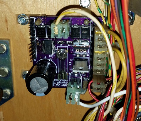
13. Here's where the connection was made for the third and final board.
14. Make sure you have replaced your GI bulbs with LEDs. If you still have incandescent bulbs installed when you turn on the power, you will blow the fuses on the GI OCD board. A few incandescents are OK, but not very many.
15. You can now turn on the machine. For each board, verify that D11 and D10 are lit solid. D9 should blink slowly (1 second on, 1 second off).
The GI lights should work, but they will be running at default settings and can be reconfigured for better results.
If you have any "DC" bulbs in wedge sockets, they may not be lighting due to the conversion to DC. These bulbs will need to be rotated in order to work.
In order to reduce board size and cost, the USB-serial part has been left off the board, and an inexpensive converter board is needed for programming. You can purchase it here or from one of many sellers on eBay, Amazon, etc.
Connect the 6-pin cable between J7 of the GI OCD and the connector on the USB-serial board. Connect a mini-USB cable between the USB-serial board and your PC. You can now use the software just as you would with a GI OCD for WPC.
You are now ready for software installation.
GI OCD Williams System 11 Pinout
Some people have found that the pinout is useful in understanding how the board should be installed, so I've included it below.
J1 - control input
1 - positive terminal (28VDC)
2 - negative terminal (GND)
J2 - controlled power
Note: pins 1 and 2 are tied together on the board
1 - input 1 (solid wire of AC input)
2 - input 2 (solid wire of AC input)
3 - key
4 - output 1 (0V when string 1 is active)
5 - output 2 (0V when string 2 is active)
6 - NC
7 - NC
J3 - AC power input
Note: pins 1 and 2 are tied together on the board
1 - striped wire of AC input
2 - striped wire of AC input
J4 - DC power output
Note: pins 1 and 2 are tied together on the board
1 - DC power output for string 1
2 - DC power output for string 2
J6 - factory programming header
J7 - user configuration header
Note: this is a 1:1 match for the Sparkfun FTDI Basic USB-to-serial module
and cheap copies such as the one available on my website or this one.
1 - GND
2 - NC
3 - NC
4 - TXD
5 - RXD
6 - NC